

Brighter Graphics as Bluebeam Sapphire Partner 2026 - For the Second Year Running
At Brighter Graphics, we proudly announce our continued recognition as a Bluebeam Sapphire Partner for 2026, marking the second consecutive year...
When it comes to construction, “close enough” just doesn’t cut it anymore. Owners expect consistent schedules, contractors want zero rework, and VDC teams need accurate, real-world data they can depend on.
Traditionally, verifying whether work was done correctly meant relying on manual methods, such as tape measures, total stations, and physical inspections. They work, but they’re slow, subjective, and leave plenty of room for human error.
According to Navigant Construction Forum, rework has always been one of the biggest drains in construction, often eating up 5 to 10% of a project's total value. Modern digital construction technologies like LiDAR and BIM help tackle the root of that problem.
LiDAR laser scanning has revolutionised the way we "build" our world. Laser-scanned, dense point clouds now give teams millimetre-level accuracy without slowing down the project. With a high level of detail, project teams can verify, compare, and correct with confidence, long before issues become costly.
When as-built data becomes a regular part of QA/QC instead of a last-minute scramble, teams can prevent conflicts before they snowball into delays and budget overruns.
This article breaks down how point clouds are reshaping construction verification and how the industry is shifting from guesswork to ground truth.
A construction point cloud is a digital 3D representation of an actual space, composed of millions (or, in many cases, billions) of accurate XYZ coordinates measured by laser scanners or LiDAR sensors. A surface point can be a small piece of a wall, a slab edge, an anchor, a pipe, or a facade panel. Taken together, these points provide a 3D representation of the real-world field conditions that can be measured.
There are two types of point cloud data:
In construction verification, structured information is key, as unstructured data only leads to confusion, misalignment, and risk to the project.
Several scanners provide grayscale intensity by default; however, colourised point clouds are becoming more popular in the industry, particularly in field conditions modelling and coordination.
Colourised LiDAR is a combination of laser depth and RGB imagery captured on board. The additional background has significant benefits:
The idea behind it is straightforward: minimise ambiguity to allow teams to make fast, confident decisions.
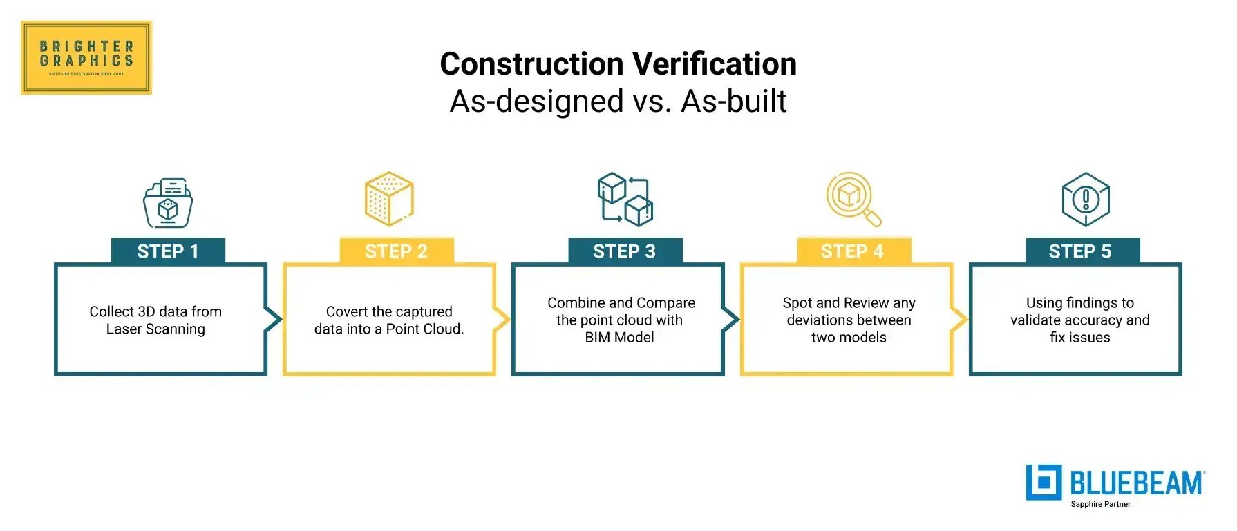
Construction verification is a technique that compares as-built point clouds to verify their correspondence with the design BIM model. It provides an answer to one crucial question: Did we create what we had planned to make?
Testing is not about model building, but quality, compliance, and detecting deviation through the following workflow:
Selecting the right approach is essential to capturing a reliable dataset. Each construction laser scanning offers distinct strengths, whether the goal is millimeter-level precision, rapid coverage, or access to hard-to-reach areas.
If you want to explore the basics of what LiDAR Laser Scanning is and how it works, read our comprehensive blog on LiDAR Laser Scanning in Construction.
Below are the primary scanning approaches used today, along with what each is best suited for.
Terrestrial Laser Scanning uses tripod-mounted laser scanners to capture highly accurate, dense point clouds of built environments. As the most precise ground-based method, TLS is ideal for millimeter-level detail and dependable QA/QC.
Best for:
Mobile SLAM systems continuously capture data as they move through a site, using simultaneous localisation and mapping algorithms to rapidly map large areas. Although not as precise as TLS, they offer unmatched speed and efficiency for high-volume interior capture.
Best for:
Drone-mounted LiDAR sensors collect data from the air, enabling rapid capture over large, elevated, or inaccessible environments. This modality is beneficial when full-structure coverage is required or when ground access is restricted.
Best for:
Close-range photogrammetry uses overlapping photographs to reconstruct detailed 3D geometry, making it ideal for textured, ornamental, or small-scale features. It is preferred when the visual richness of surfaces matters more than depth precision.
Best for:
Reliable construction verification is based on point cloud registration. If the dataset does not accurately reflect reality, then analysing deviations cannot be helpful.
Registration processes can be:
Noise and outliers are eliminated after the alignment. The resulting product is a coherent, organised point cloud, with each scan aligned to the project coordinate system. This is obligatory for both credible tolerance tests and deviation maps.
Laser-scanned construction data supports multiple downstream workflows, but two of the most commonly confused are Scan-to-BIM and Scan-vs-BIM. Although the terms sound similar, they serve entirely different project goals.
The sections below clarify where each workflow fits, what it produces, and how laser scanning verification is applied.
Scan-to-BIM is the process of using point cloud data to create a BIM model of existing conditions. The goal is model generation, transforming real-world geometry into accurate digital BIM elements for use in design, coordination, or renovation.
Scan-to-BIM is typically used for:
Workflow:
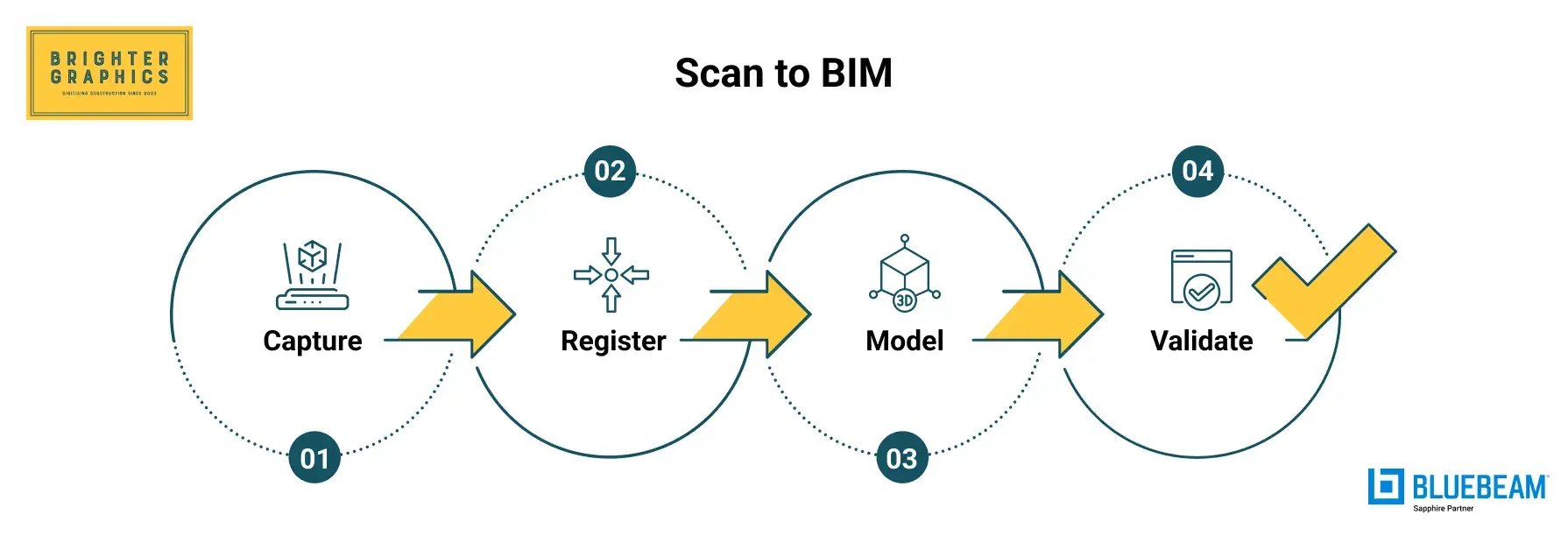
As its name suggests, the modelling stage in Scan to BIM (Scan to Model) comes once the scanned data is available.
Scan-vs-BIM, also known as laser-scanning verification (construction verification or BIM verification), is the process of comparing an as-built point cloud with the as-designed BIM model. The objective is to ensure quality control, identify deviations, assess clash risks, and address installation issues before they impact the schedule or cost.
This process produces objective, defensible QA/QC documentation. Colour-coded deviation maps (e.g., green = in tolerance, red/blue = out of tolerance), numerical callouts, and clash-risk indicators eliminate subjective debate. Instead of arguing over whether something is “close enough,” teams can rely on verified data to resolve issues efficiently.
The method is used during active construction verification for:
Workflow
.webp?width=1790&height=669&name=Scan%20vs.%20BIM%20(Verification).webp)
As mentioned above, this is how the Construction Verification (Scan vs. BIM) workflow compares the as-built model with the as-designed model (as the BIM model is already created during the Scan to BIM process earlier):
|
Category |
Scan-to-BIM |
Scan vs BIM (Laser Scanning Verification) |
|
Primary Purpose |
Create a BIM model of existing conditions from point clouds |
Compare as-built point clouds against the design BIM |
|
When It’s Used |
Renovations, refurbishments, heritage, brownfield sites, existing buildings |
Active construction, QA/QC, prefabrication checks, milestone validation |
|
Data Input |
Point cloud => then modelled into Revit/other BIM platforms |
Point cloud => directly compared to design model |
|
Core Workflow |
Capture => Register => Model => Validate |
Capture => Register => Compare => Visualise |
|
Output |
Parametric BIM model + documentation |
Deviation maps, QA/QC reports, signed colour maps |
|
What It Answers |
“What exists in this building?” |
“Is the work built exactly to the design?” |
|
Key Value |
Accurate digital representation of existing conditions |
Early detection of drift, reduced rework, faster closeout |
|
Audience |
Designers, architects, facility managers |
Contractors, VDC/BIM teams, owners |
|
Typical Tolerances |
Depends on modelling spec (LOD/LOI) |
Highly precise: mm-level deviation analysis |
|
Examples |
Creating BIM for a 1970s hospital |
Capturing a core wall after pour, checking hanger layout |
QA/QC processes in complex projects can tend to be reactive, i.e., the team learns about a problem only when a clash between trades occurs or when a problem is identified during final inspection. This is verified by laser scanning, which provides teams with real-time, measurable reality checks.
Verification is made with the help of:
This produces objective, traceable documentation. No opinions. No disputes. Just hard data.
A deviation map might show:
In all situations, disclosing such variances early on avoids time-consuming rework and keeps the project on track.
Most clashes don’t happen because the BIM model is wrong—they happen because real-world field conditions shift over time. A duct can sag 10 mm below expectations, a sleeve can shift during installation, a hanger can end up slightly off-centre, or a slab edge might be just 1 mm out of position. These slight deviations seem harmless at first, but they stack up quickly once multiple trades begin installing their work.
Field conditions modelling tackles this problem at the source. By capturing as-built point clouds at key milestones, teams get a verified, up-to-date view of what actually exists onsite, not what the drawings assume is there. This directly reduces coordination problems because:
Common examples of field-condition checks include:
When teams rely on point clouds to guide decisions, field conditions stop being a risk and start becoming a strategic advantage.
Modern buildings often feature non-traditional shapes: spirals, sweeping curves, domes, sloping slabs, tunnels, and other free-form architectural elements. These complex geometries are complicated (and often impossible) to measure manually. Even traditional total stations struggle when surfaces bend in multiple directions or don’t follow standard angles.
Construction laser scanning solves this problem with density, fidelity, and speed:
One of the biggest winners here is the classic MEP “spaghetti room.” With dense point clouds, teams can see every pipe, duct, conduit, cable tray, and tight clearance, without relying on manual measurements or walking the site with a tape and flashlight.
This level of precision dramatically reduces miscoordination and eliminates the “field improvisation” that often leads to costly fixes later. Laser scanning doesn’t just document reality, it makes complex spaces understandable and buildable.
In construction, the headache usually isn’t scanning: it’s receiving messy, unorganised point clouds that no one can figure out. Poor registration, incorrect labeling, and inconsistent data… all of this makes verification nearly impossible.
A reliable downstream workflow depends entirely on the quality of the deliverables. If the package isn’t clean, structured, and usable, no team (VDC, BIM, or trades) can trust it.
Laser scanning outputs can be delivered at different levels of detail depending on how the data will be used. From raw, unprocessed scans to fully developed BIM models, each tier serves a unique purpose in verification, coordination, and downstream project workflows.
The four main deliverable types include:
Raw scans are the most basic deliverable tier and represent the scanner's untouched output. Delivered in formats such as E57, LAS, or RCP, these files contain the original point data with no alignment, cleanup, or processing applied. They are typically used for archival purposes or by teams that prefer to run their own registration workflows.
Processed point clouds are the standard working files for most verification and coordination workflows. At this stage, the scans have been fully registered, cleaned, and aligned to a consistent coordinate system, making the data immediately usable across project teams.
A complete processed package usually includes:
Meshes represent a more continuous and visually intuitive surface model derived from the point cloud. They are handy for irregular or non-linear surfaces, such as facades, tunnels, heritage structures, and freeform architectural geometry.
By converting dense points into a connected surface, meshes make it easier for design and construction teams to interpret complex shapes that would otherwise be difficult to visualise or model directly from raw points.
Parametric BIM models are the most advanced tier of deliverables, where the point cloud has been fully interpreted and transformed into intelligent elements within tools such as Revit, SolidWorks, or similar platforms.
Rather than representing geometry as points or surfaces, these models consist of walls, columns, ducts, equipment, and other components with definable attributes. This level of deliverable is typically used for design updates, fabrication, clash detection, and long-term asset management, offering the highest degree of usability and integration across project workflows.
A bad scan is enough to stop verification measures, lead to misinterpretation, and produce a false alarm. The choice of an appropriate partner is of utmost importance, particularly for highly sensitive projects.
These are the must-have factors you must evaluate before signing a laser scanning, BIM, or construction verification partner:
Questions to Interrogate Before Contracting a Scanning or Verification Partner
The scan price varies according to several technical and logistical factors. Although this article does not provide actual figures (due to multi-factor variability), the following drivers can help you determine the scope, effort, and turnaround time involved in the scanning or verification project:
Teams ought to consider, rather than thinking about price per square foot:
Remember that laser scanning for the Scan to BIM process is different from laser scanning verification (Scan vs. BIM or construction verification).
*Refer to the Scan to BIM and Scan vs. BIM section at the start of this blog for more clarity.
As a project owner or a contractor, you must highlight your needs clearly to the outsourced team, whether you need just scans with a structure point cloud, follow the Scan to BIM process for complete modelling, or already have a BIM model that you want to verify with Scan vs. BIM (laser scanning verification).
Laser scanning, BIM coordination, and verification are not simply costs; they are catalysts for predictable, high-quality project management and delivery.
Brighter Graphics Digital Engineering is your go-to partner for everything you need, offering structured, visualisation-ready point cloud data for robust construction or BIM verification. Our Digital Engineering team has combined expertise in laser scanning, 3D modeling, and BIM verification to deliver end-to-end digital engineering solutions that ensure accuracy, compliance, and efficiency in construction.
For more detailed scope and cost estimates, contact our team directly and leverage our 30 years of experience serving the Architecture, Engineering, Construction, and Operations (AECO) industry, capable of meeting today's digital construction requirements.
Many of the verification issues have not been caused by construction; instead, they are due to poor scanning practices. The most prevalent pitfalls and how to avoid them are listed below.
Deviations cannot be rectified in case the scanning occurs after the walls are closed or the concrete has already cured.
Mitigation: Scan predetermined milestones, such as post-pour, post-install, and pre-close, to ensure problems are corrected immediately.
Without control points, point clouds can drift or shift, leading to spurious deviations.
Mitigation: Establish, stabilise, and verify the survey control and coordinate system before scanning.
Noisy, broken geometry, and imprecise comparisons are often the result of sparse or inconsistent data.
Mitigation: Ensure a 40-60% overlap, good density, and even station spacing.
Raw, unprocessed point clouds are a waste of time and cause misunderstandings.
Mitigation: Always provide formatted point cloud information with metadata, station hierarchy, and naming conventions.
Although colour is not always obligatory in any context, its absence makes interpretation even more difficult.
Mitigation: Record colourised point clouds to be coordinated, routed in MEP, and perform geometric complex work.
Construction leadership nowadays does not require additional reports and more opinions. They need ground truth.
The absolute truth, the actual truth, the truth that cannot be disputed, is presented by laser scanning and as-built point clouds all the time.
Our Digital Engineering team brings you the well-coordinated, visualisation-ready workflows and technologies supporting all the processes from capture to model, manage, and handover, spanning:
Being accurate is no longer a choice; it is a necessity. Using digital technologies in your construction projects, the building process becomes more certain, coordination gets smarter, and the project is built as you designed, not a millimetre off.
Start your future-ready digital construction journey today and stay ahead of growing industry competition.
Q1. What’s the difference between scan-to-BIM and scan vs. BIM (laser scanning verification)?
Scan-to-BIM generates a BIM model out of point clouds. A Scan vs. BIM comparison involves comparing the as-built point cloud with the design model for QA/QC. They serve different purposes, such as modelling versus verification, and must not be confused with one another.
Q2. How accurate are as-built point clouds for construction?
Point clouds can provide millimetre-level accuracy, depending on the scanner and scanning process. When done correctly, they are accurate enough for checking structures, MEP installations, and prefabricated components.
Q3. When should we schedule construction laser scanning during the project?
Scanning should be done at key milestones: after concrete pours, before ceilings are closed, before facades are installed, and before prefabricated components are delivered. Early scanning helps avoid mistakes and prevents delays later.
Q4. Can point clouds handle complex geometries, including outdoor and indoor scanning?
Yes. Laser scanning can handle curves, tunnels, freeform shapes, and dense MEP areas. Indoor TLS and outdoor drone LiDAR can be used together for full coverage.
Q5. What formats do owners and designers prefer for structured point cloud data?
The most common formats are E57, LAS, and RCP. Structured clouds also include scan-station information, control points, and coordinate references so that teams can use the data directly without extra work.
Q6. Do we need colourised LiDAR, or is grayscale enough?
Grayscale works, but colourised point clouds are much easier to read and interpret. Colour helps identify materials and makes coordination and remote review much simpler.
Q7. How do laser scanning services price projects (and what affects turnaround)?
Costs depend on site area, complexity, point density, access, deliverables, control, and schedule. Faster turnaround usually requires more staff and longer hours. Even though scanning costs money upfront, it saves time and avoids expensive rework later.
At Brighter Graphics, we proudly announce our continued recognition as a Bluebeam Sapphire Partner for 2026, marking the second consecutive year...
By 2026, the global construction market will enter a significant paradigm shift, characterised by precision, data-driven processes, digital twins,...
The new Bluebeam Revu update, version 21.8, is now available. The latest version focuses on simplifying workflows, improving collaboration, and...